

Let's think about this morning. You get up, the alarm goes off, you turn on the light, charge your phone, and maybe heat breakfast. Everything is possible because of electric circuits that are working behind the scenes. For most of us, these circuits are used without thinking. So what is an electric circuit? Let's break it down.
An electric circuit is a complete and closed path through which electrical current can flow. When an electric circuit is open, meaning that the path is broken anywhere, the current stops, and the circuit will not work. Think about it like this — think about water flow. If the water pipe is broken, it will not flow.
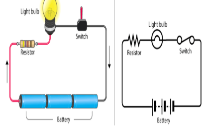
Every working circuit requires at least three parts:
Electric current is the flow of electric charge through a conductor. In most circuits, tiny particles called electrons carry this charge. They move through metal wires because metals have free electrons that can move easily.
Unit of measurement: amperes (A), usually shortened as amps.
Measured with an ammeter (connected in series).
I = Q ÷ t
I = current (A), Q = charge (coulombs, C), t = time (seconds)
Voltage is the amount of energy supplied to each unit of charge by the battery, or the energy given up by each unit of charge as it passes through a circuit component. Think of voltage as the energy source that pushes the current around the circuit.
Unit of measurement: volts (V)
Measured with a voltmeter (connected in parallel).
V = W ÷ Q
V = voltage (V), W = work done/energy (J), Q = charge (C)
Resistance is the opposition to the flow of current in a conductor.
Unit of measurement: Ohms (Ω)
Measured with an ohmmeter.
V = I × R
V = voltage (V), I = current (A), R = resistance (Ω)
Georg Ohm established that for a metal conductor at constant temperature, the current through it is directly proportional to the voltage across it.
If voltage increases, current increases. If resistance increases, current decreases.
Ohmic conductors: Plain resistors (follow Ohm's Law)
Non-ohmic conductors: Light bulbs (resistance changes with temperature), diodes (do not follow the rule)
In series circuits, all elements are connected in a single circle, forming just one path for current to flow.
R_total = R₁ + R₂ + R₃
Example: Old Christmas lights — a single blown bulb would cause the entire string to go out.
In parallel circuits, elements are connected to each other, providing multiple current paths.
1/R_total = 1/R₁ + 1/R₂ + 1/R₃
Example: Home circuits — switching off one bulb does not affect other bulbs.
P = V × I
P = power (watts, W), V = voltage (V), I = current (A)
Alternative formulas: P = I² × R or P = V² ÷ R
Power shows how fast electrical energy is being used or transferred. A more powerful device consumes energy at a greater rate per second.
Example: A phone charger operating at 5V with a current of 2A consumes 10W of power.
E = P × t or E = V × I × t
E = energy (joules, J), t = time (seconds)
Energy is the total work done in a circuit over a given amount of time.
Your electricity bill at home is measured in kilowatt-hours (kWh) — a larger unit of the same quantity.
In physics, we use circuit symbols instead of drawings. This enhances clarity and is universal, no matter your location.
When drawing circuit diagrams, use straight lines and right-angle bends. A carefully laid-out circuit is easier to understand and analyze.
Every electronic device you interact with, from a simple torch to a sophisticated computer, is built on the concepts covered in this lesson. Understanding current flow, the voltage that pushes it, and the resistance that controls it is essential for designing, repairing, and evaluating the technology around you.
| Quantity | Symbol | Unit | Measuring Instrument |
|---|---|---|---|
| Current | I | Ampere (A) | Ammeter (in series) |
| Voltage | V | Volt (V) | Voltmeter (in parallel) |
| Resistance | R | Ohm (Ω) | Ohmmeter |
| Power | P | Watt (W) | - |
| Energy | E | Joule (J) | - |